To determine the shear stresses at specific locations in a beam due to external loading. Beam ABC...
Question:
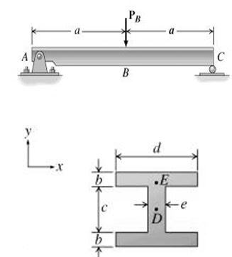
To determine the shear stresses at specific locations in a beam due to external loading. Beam ABC is subjected to the loading shown, where P{eq}_B {/eq} = 75.0 kN. The measurement corresponding to the half-length of the beam is a = 4.50 m. For the cross-section shown, b = 75.0 mm , c = 125.0 mm , d = 100.0 mm , and e = 60.0 mm . Point D is located at the centroid of the cross-section and point E is located directly above the transition between the web and the top flange.
Part C - Shear stress at point D Determine the shear stress, {eq}\tau_D {/eq}, at point D that corresponds to the maximum shear force along the length of the beam. Express your answer to three significant figures and include appropriate units.
Part D - Shear stress at point E Determine the shear stress, {eq}\tau_E {/eq}, at point E that corresponds to the maximum shear force along the length of the beam.
 |
I-Beam
An I-Beam consists of two horizontal sections called flanges and one vertical section called the web. The shear stress induced in the I-Beam is maximum at the centroid or the neutral axis of the beam and the shear stress is zero at the upper surface of the top flange and at the bottom surface of the bottom flange.
Answer and Explanation: 1
Become a Study.com member to unlock this answer! Create your account
View this answerThe beam ABC is a simply supported beam, carries at Point load at the mid of the beam
By using force balance equation
{eq}\begin{align} R_{A}+R_{B}...
See full answer below.
Ask a question
Our experts can answer your tough homework and study questions.
Ask a question Ask a questionSearch Answers
Learn more about this topic:

from
Chapter 2 / Lesson 2What is shear stress? View the shear stress formula, shear stress units, and shear stress equations. See shear stress symbols and the shear stress definition.
Related to this Question
- To determine the shear stresses at specific locations in a beam due to external loading. Beam ''ABC'' is subjected to the loading shown, where PB = 90.0 kN. The measurement corresponding to the half-length of the beam is a = 5.00 m. For the cross-section
- Beam ABC is subjected to the loading shown, where PB = 75.0 kN . The measurement corresponding to the half-length of the beam is a = 3.50 m . For the cross section shown, b = 65.0 mm , c = 150.0 mm ,
- For the beam and loading show, consider section n-n and determine the shearing stress at points A and B.
- The cross section of a beam is shown. The shear force in the beam is 150 KN. Determine the shear stress at points "a" and "b". All the dimensions are in mm.
- The beam is supporting a distributed load of w = 1170 lb/ft. Determine the internal resultant loading acting on section b-b through the centroid C on the beam.
- For the beam and loading shown, consider section n-n and determine the shearing stress at points (a) and (b). ?a = ?? ksi ?b = ?? ksi
- For the beam and loading shown, consider section n-n and determine the shearing stress at point a.
- The rigid bar D E F is welded to a dteel bar A B . For the loading shown, determine (a) the equations defining the shear and bending moment at any point of the beam, (b) the location and magnitude
- Consider the cantilever beam and loading shown in the figure, where d=7.00 ft, w=562 lb/ft, and w=310 lb/ft. Determine the magnitudes of the internal loadings on the beam at point C.
- The attached figure shows a simply-supported beam of total length 8 m loaded by two concentrated forces of 10 kN each. The beam cross-section is 100 mm X 100 mm square. Find the magnitude and exact location of the maximum tensile stress due to bending. He
- For the beam and loading shown, consider section n-n and determine the shearing stress ( ? a (?a and ? b ) ?b) at point a a and point b b.
- The shear force diagram of a beam is shown. Determine the loading on the beam and draw the bending moment diagram, assuming that no moments acts as loads on the beam.
- To determine the deflection and slope at two positions along a beam's length using the method of superposition. Beam ABCD is subjected to the loads shown. Let w = 8.50 kip/ft , P = 6.50 kip , M = 7.50
- Internal Loading Due to a Variable, Distributed Load Consider the cantilever beam and loading are shown in the image below where d=15.0 ft, wB=870 lb/ft, and wA=390 lb/ft. (Figure) Determine the magnitudes of the internal loadings on the beam at point C.
- For the simply supported beam, We would like to determine the internal loads at point E, which is halfway between B and C. Given: T = 36 kN, a= 21 degrees M= 24 kN-m 1) Calculate the Internal Normal force at point E? 2) Calculate the internal shear for
- The distributes load act on the beam as shown. Determine the magnitude of the equivalent resultant force and specify where it acts, measured from point A.
- Determine the resultant of the distributed load acting on the beam shown, and locate its line of action with respect to the support. The loads applied are W 1 W1 = 160 lb/ft and W 2 W2 = 25 lb/ft. T
- The equivalent resultant force acting on the beam is zero and the resultant couple moment is 9.5\ kN \cdot m clockwise. (a) Determine the Lenght b of the triangular load. (b) Determine the position of the triangular load on the beam.
- A distributed load W(x)=4x^1/3 acts on the beam AB shown in Figure below, where x is measured in meters and w is in kN/m. The length of the beam is L = 2 m. (i) Find the moment of the resultant forc
- For the beam and loading shown, consider section n-n and determine the shearing stress at (a) & point (b).
- Part A: Internal loading due to a variable, distributed load Consider the cantilever beam and loading shown in the image below where d=9.0 ft, wB=410 lb/ft, and wA=230 lb/ft. Determine the magnitude
- The shear force diagram of a beam is shown on the figure. Determine the loading on the beam and draw the bending moment diagram, assuming that no moments acts as loads on the beam.
- A distributed load w(x)=2x\frac{1}{2} acts on the beam ''AB'' shown in the figure, where x is measured in meters, and w is in kN/m. The length of the beam is L= 4 m. Find the magnitude of the resultant force and the x coordinate defining its line of actio
- A 5.0-'m''-long simply supported timber beam carries two concentrated loads as shown. the cross-sectional dimension of the beam is also shown. (a) A section ''a''-''a'', determine the magnitude of the shear stress in the beam at point ''H''. (b) A sectio
- Determine the elastic curve for the beam shown. Specify the slope and vertical deflection in the middle of the beam when it is subjected to triangular load distribution.The beam is made of Steel havin
- the beam is subjected to the distributed loading. Determine the length b of the uniform load and its position a on the beam such that the resultant force and couple moment acting on the beam are zero
- The concentrated load F = 17.5 kN acts at the beam midpoint. The distributed load f = 10.5 kN/m acts over the middle one-half of the beam (as shown). The beam length is L = 21 m. Determine the magnitude of the internal shear force at the midpoint of the b
- Consider the cross section of a beam shown below. Assume the beam is experiencing an internal shear force of 5.000 N. Using this information, calculate the magnitude of the bending shear stress at th
- Consider the cross section of a beam shown below. Assume the beam is experiencing an internal shear force of 5.000 N. Using this information, calculate the magnitude of the bending shear stress at the
- For the steel truss E = 200 GPa and loading shown, determine the deformation of the members AB and AD, knowing that their cross sectional areas are 2400 mm^2 and 1800 mm^2, respectively.
- Consider the cantilever beam and loading shown in the image below where d=13.0 ft, wB=470 lb/ft, and wA=210 lb/ft. Determine the magnitudes of the internal loadings on the beam at point C.
- The beam is supporting a distributed load of \omega 1140 Ib/ft. Determine the resultant internal loadings acting on section b-b through the centroid C on the beam.
- The 12m long beam shown bellow supports a 2.7 kN load at a = 7m. Determine the maximum shear stress in the beam. T section dimensions b = 180 mm, d = 60 mm, t_f = 20 mm, t_w = 18 mm.
- For the distributed load shown below, determine the equivalent force's magnitude and location, measured from point O. Let a = 1.43 kN/m3 , b = 3.30 kN/m2 , and L = 2.30 m .
- The equivalent resultant force acting on the beam is zero and the resultant couple moment is 8 kN-m clockwise. a. Determine the length b of the triangular load. b. Determine the position a of the tria
- The beam is subjected to the loading shown. (a) Determine the internal shear and moment of the beam as functions of x (with origin at point A) (b) Plot the shear and moment diagrams.
- A steel cantilever beam is loaded as shown. The beam is a W21x50. The modulus of elasticity is 29 x 10^6 psi. The length of the beam L is 15 ft. P = 7.5 kip. Determine: a. Sketch the shear and moment
- For the beam and loading shown, consider section n - n and determine the shearing stress at (a) Point a, (b) Point b.
- The equivalent resultant force acting on the beam is zero and the resultant couple moment is 12.5 kN-m clockwise. A) Determine the length ''b'' of the triangular load. B) Determine the position ''a''
- For the beam and loading shown in the figure , consider section ''n''-''n'' and determine the shearing stress at (a) point a,(b) point b.
- For the beam and loading shown determine the magnitude and location of the resultant of the distributed load.
- The simply supported beam consists of a W410\times 60 structural steel wide-flange shape \left ( E=200 GPa; I= 216\times 10^{6}mm^{4} \right ) . For the loading shown, determine the beam deflection at point ''C''. Assume P = 71 kN, w= 97 kN/m, L_{AB}=L_{B
- The beam is subjected to the distributed loading. Determine the length b of the uniform load and its position a on the beam such that the resultant force and couple moment acting on the beam are zer
- The simply supported beam consists of a W410 60 structural steel wide-flange shape (E = 200 GPa: I = 216 10 6 mm 4 ). For the loading shown, determine the beam deflection at point C. Assume P
- For the beam and loading shown, determine (a) the magnitude and location of the resultant of the distributed load, (b) the reaction at the beam supports.
- Take that w_0 = 4.8 kN/m. Replace the distributed loading with an equivalent resultant force. Specify its location on the beam measured from point O.
- The simply supported beam shown in figure consist of a W410x60 structural steel wide-flange shape (E=200 GPa; I=216x10^6 mm^4). For the loading shown, determine the beam deflection at point B.
- For the beam and loading shown, consider section ''n-n'' and determine the shearing stress at (a) point a, (b) point b. \tau _{a} = _____ksi \tau _{b} = _______ksi.
- For the beam and loading shown below, consider section n-n and determine: (a) The largest shearing stress at that section. (b) The shearing stress at point a
- The W8x48 (I=184 in^4) cantilevered beam is made of steel (E=10x10^6 psi) and is subjected to the loading shown. The beam is fixed at location B. Determine the deflection at point A.
- For the beam and loading shown below, consider section n-n and determine (a) The largest shearing stress in that section. (b) The shearing stress at point a. (Express your answer in significant figur
- The beam is subjected to the distributed loading. Determine the length b b of the uniform load and its position a a on the beam such that the resultant force and couple moment acting on the beam are
- Determine the resultant internal loadings in the beam at cross sections through points D and E. Point E is just to the right of the 15-kN load.
- Consider the cross-section of a beam shown in the figure below. Assume the beam is experiencing an internal shear force of 5,000 N. Using this information, calculate the magnitude of the bending shear
- The simply supported beam is made of A-36 steel and is subjected to the loading shown. If P=27 kN and w=6 kN/m, determine the deflection at its center C. I=0.1457(10^-3) m^4.
- The distributes load and concentrated force act on the beam as shown. Determine the magnitude of the equivalent resultant force and specify where it acts, measured from point A.
- A 4-5 -''m'' long simply supported timber beam carries two concentrated loads as shown. The cress sectional dimensions of the beam are also shown. (a) At section a-a, determine the magnitude of the shear stress in the beam at point ''H''. (b) At section a
- For the beam and loading shown, Consider section n-n and determine (a) The largest- shearing stress in that section. (b). The shearing stress at point a.
- The beam is subjected to a shear force of 80 kN. Determine the shear stress developed at point ''A''.
- The beam is subjected to a shear force of 140 kN. Determine the shear stress developed al point ''A''.
- Consider the beam in the figure below. Take w = 15 kN/m. A) Determine the internal normal force at point C in the beam. B) Determine the internal shear force at point C in the beam. C) Determine th
- Determine the internal shear force V (in kN) that exists int he beam at the following locations: a) x = 1 m, b) x = 7 m.
- Determine the resultant force and specify where it acts on the beam measured from A. Assume F=600 lb.
- An extruded aluminium beam has the cross section shown. Knowing that the vertical shear in the beam is 240 kN, determine the shearing stress at point a.
- For the beam shown, draw the shear and bending moment diagrams. Then calculate the maximum tensile bending stress. Indicate where the stress occurs on the cross-section and along the length of the beam.
- For the beam with loading shown below, determine: a.The reactions at the supports. b.By cutting the beam at a point located 8 ft to the right of point A: the internal shear and moment. c.By-cutting th
- For the beam and loading shown, determine (a) The magnitude and location of the resultant of the distributed load, (b) The reactions at the beam supports.
- For the beam and loading shown. determine the magnitude and location of the resultant of the distributed load and the reactions at the beam supports.
- A T-shaped beam with an overhang is supported and loaded as shown in the figure. Calculate: (a) The shear stress at a point 2 m from support ''A'' and 25 mm from the top of the beam. (b) The greatest shearing stress.
- The beam is bolted or pinned at A and rests on a bearing pad at B that exerts a uniformly distributed loading on the beam over its 2-ft length. Determine the shear and bending moments along the beam u
- For the cantilever beam and loading shown, a) Evaluate beam reactions. Derive equations for the shear force V and the bending moment M for any location in the beam. (Place the origin at point A.)[ An
- For the beam and loading shown, consider section n-n and determine: a) the largest shearing stress int he section, b) the shearing stress at point a.
- (A). Determine the shear stress at point B on the web of the beam located at section a-a. Express your answer to three significant figures and include appropriate units.(B). Determine the shear stress
- A cantilever beam supports the load shown. The cross sectional dimensions of the shape are also shown. Assume a =0.4m, P_A = 2.5 kN, P_B = 7.0 kN, P_C=3.5 kN, d=110 mm, b=95 mm, t_f=7 mm, t_w=5 mm. De
- An extruded aluminium beam has the cross section shown. Knowing that the vertical shear in the beam is 150 kN, determine the shearing stress at point a. Dimensions are in mm.
- A beam with the cross-section shown is subjected to a vertical shear of 30 kN. Determine: (a) The largest shearing stress in that section, (b) The shearing stress at Point a .
- The beam is subjected to a shear of V = 12.5 kN. Set w=125 mm. (a) Determine the web's shear stress at ''A''. (b) Determine the web's shear stress at ''B''.
- A beam embedded at one end is loaded by a distributed load of w N/m, (1) Show that the internal moment at x is M(x) = -w(L-x)^2/2 (2) Show that the elastic curve is y= -wx^2 (x^2-4Lx+6L^2)/24EI (3) Determine the end deflection,
- An extruded aluminum beam has the cross-section shown. Knowing that the vertical shear in the beam is 170 kN, determine the shearing stress at point a .
- If rope BC will fail when the tension becomes 60 kN: A) Determine the greatest vertical load F that can be applied to the beam at B. Neglect the thickness of the beam. B) Determine the magnitude
- An A-36 W 10 39 beam supports the loads shown. Sketch the shear-force and bending-moment diagrams including both the applied loads shown and the self-weight of the beam. Calculate the transverse s
- A beam is built up by gluing three 2 in.\times 4 in. (actual dimensions) boards together as shown below. If this beam is subjected to a transverse shear load of 2000 pounds, determine the shear stress resisted by the glue and also determine the maximum sh
- The beam is subjected to a shear force of V = 130 kN. Determine the shear stress at point A.
- The simply supported beam consists of a W410 * 60 structural steel wide flange shape ( E = 200 G P A , I = 216 ? 10 6 m m 4 ), For the loading shown, determine the beam deflection at point C . As
- Consider the beam consist loaded as shown in figure below. a) Draw the shear and moment diagrams for this beam, determine the shear and moment through the beam as functions of x and determine the maxi
- The internal shear force V at a certain section of an aluminum beam is 12.3 kN. If the beam has the cross section shown (assume a=37 mm, bf=78 mm, tw=tf=6 mm, d=74 mm), determine: (a) the shear stress
- For the beam and loading shown, consider section n - n and determine the shearing stress at a) point a, in ksi. b) Point b, in ksi.
- In the loading and the beam shown below, consider section n-n and determine (a) The largest shearing stress in that section. (b) The shearing stress at point a.
- Consider the beam in the figure below. Take P = 15 kN. 1. Determine the internal normal force at point C in the beam. 2. Determine the internal shear force at point C in the beam. 3. Determine the
- The figure shows the cross section of a simply supported beam that carries a uniformly distributed loading of intensity 200 lbf/ft over its entire length L. If the allowable shear stress is =80 psi, determine the largest allowable value of L.
- Internal load in beams. p=8000 lbs q=300 lb/in L 1 L1 = 60 in L 2 L2 = 30 in L 3 L3 =15 in L 4 L4 =50 in Determine the shear force and bending moment at the cross-section located at x=50 in fro
- For the beam and loading shown, consider section n-n and determine the largest shearing stress in that section.
- The Howe truss is subjected to the loading shown in. Suppose that F = 7 kN. (a) Determine the force in members ''GH'' and state if the member is in tension or compression. (b) Determine the force in member ''BC'' and state if the member is in tension or c
- Determine the internal shear force and moment acting at point C in the beam.
- A simply supported beam with spans of a=1.5 m and b=5.5 m supports loads of w=40 kN/m and P=30 kN, as shown. At the section of maximum shear force, determine the horizontal shear stress at a distance
- For the beam and loading shown, Provide the shear and bending moment diagrams and determine the magnitude of the largest bending in the beam if k =0.5.
- Consider a simply supported beam made of a 2.5" x 2.5" A36 bar. The beam is 12 ft long and loaded in the middle with a 10 lb concentrated load. a. Using the general shear formula, determine the maximum shear stress in the bar and then state whether the b
- The simply supported beam is made of A-36 steel and is subjected to the loading shown in the figure. Suppose that P = 20.2 kN. E = 200 GPa and I = 0.1457 (10^{-3}) m^4. Determine the deflection of the beam at its center ''C''.
- Consider the beam shown in the figure. The roller at A and the pin at B can support a load up to 4 kN and 8 kN , respectively. Determine the maximum intensity of the distributed load w, measured in k
- Learning Goal: To determine the deflection and slope at two positions along a beam's length using the method of superposition. Beam ABCD is subjected to the loads shown. Let w = 5.50 kip/ft , P = 7.50